


I can't believe I've been sitting on this post for over a year.
During senior year of college (2014) I was head of electrical engineering for the marine technology club and designed the control system for our ROV, Draugr. I ended up receiving credit for it as an independent study course and later wrote a paper which won a prize in the IEEE student paper contest.
The goal of the competition that year was to investigate a mockup shipwreck on the floor of a 17' pool. The club partnered with the Society for Mechanical Engineers to build the frame on the mechanical engineering department's waterjet table provided they could have use of the ROV for their own manufacturing design competition.
The body of the ROV was constructed from three flat HDPE sheets connected by brackets. Buoyancy was provided by a large PVC tube at the top of the ROV which also served to strengthen the frame and keep the center of buoyancy high above the center of mass. Under the deck was a metal plate with regularly spaced holes for mounting equipment and ballast trim weights.
Propulsion was provided by six bilge pump motors with attached propellers and shrouds. Instead of the previous year's incredibly massive metal drybox we decided to use an off the shelf plastic otterbox to house the electronics. Holes were drilled into the side and the seacon waterproof electrical fittings from the previous year's ROV were installed.
The overall footprint of the ROV fit within a rectangular box with rounded edges approximately the size of a all-in-one office printer which could easily be lifted by a single person leaning over the edge of a swimming pool, dock or boat.
The design of the electrical system diverged wildly from previous years. We opted for a two board design: one small carrier for a 48-12V DC-DC step-down converter and another large board holding the control system, power regulation, communications and motor drivers. The tether was a two cable system: one carried 48V power and the other was an extended length (something like 50') USB cable. This allowed both control signals and video to be carried by the same cable. In order to actually make the 50' run the USB cable required a mid-length repeater that was housed in-line within waterproof plastic potting (we double potted it ourselves just to be sure).
The whole super-long USB tether idea came about due to an image processing mission objective given by MATE as part of that year's challenge. Traditionally most ROVs in our class used analog cameras connected to a monitor at the surface. We had to make panoramic images of objects on the pool's floor and waterproof webcams were far cheaper than building a control console with an analog image capture card in it. At first we considered placing an embedded computer like a RasPi or beaglebone onboard the ROV and talking to it over ethernet but in the end we went with this USB-supertether concept for some reason that I can't really remember now.
Anyway, the motherboard had a built-in USB hub (more about that later) that had an internal connection to an atmega microcontroller. The computer at the surface on the other end of the tether would see a USB-serial device and could command the motors to spin, sensors to take measurements, actuators to move, etc. The hub also had breakouts for other USB devices onboard the ROV, namely webcams. We weren't even limited to one webcam, in fact I went a bit overboard and attached two waterproof webcams about 2.5" apart and fed them into a pair of stereo vision goggles I build out of a cellphone, cardboard and a couple fresnel lenses. (This was pre-google cardboard so we couldn't just order one.)
VR undersea adventures! Unfortunately it was a gimmick and we didn't have time to make the camera mounts steady (they were made of velcro for easy changes) or the stereo goggles reliable enough to use off the test bench. You can see the how ridiculously adorable the ROV looked with the dual mounted cameras though.


The surface control console we ended up settling with was a laptop running an application one of our team members wrote that showed the webcam steam onscreen with the ability to save image snapshots. It also took commands from an xbox controller and passed them on to the microcontroller to run the motors. It ended up being simple and intuitive enough that we allowed random people to use it in one of the school's fountains.
In the end we didn't qualify for the national competition due to an electrical failure. After several hours of successful testing at the regional MATE competition we attempted to preform our qualification trial. While transferring the ROV to the qualification pool we forgot the battery supply at our table. Instead of walking across the room to retrieve them another nearby team (not naming any names) offered us their batteries for the qualification test. Long story short, we plugged them in and they killed the ROV. We were unable to restart it despite subsequent attempts using our own batteries.
During post-mortem testing that evening at metrix we realized that our batteries had internal current limiters that would only allow them to provide a few amps max. The batteries we borrowed had no such limitation. Upon powerup the inrush current was considerable and the powerful batteries were all too happy to provide enough current to burn out a trace on one of our PCBs. Here's where the failure gets a bit complicated.
Due to a design oversight on my part the specific package of the USB hub IC required for the motherboard was out of stock. As an alternative we purchased a small USB hub which required modification (USB connectors were too large to be passed directly through the waterproof cable penetrators and had to be cut). Space was so limited within the drybox that we couldn't simply reattach the ends of the USB cables and plug them into the hub, instead we had to wire them directly into the electronics with terminal blocks.
We desoldered the USB hub's ports and created a simple PCB on copper-clad board that converted them to terminal blocks to which we attached the stripped USB cables. It was on this board that one of the overly-thin traces burned out, cutting off power to the in-line repeater on the tether cable.
The failure could have been avoided numerous ways: the onboard hub could have been constructed with the proper IC package, the trace on the impromptu PCB could have been thicker, the drybox could have been large enough for real USB connections, we could have walked across the room to retrieve our own batteries, we could have had a replacement electronics package in the event of failure or the design architecture of the ROV could have eliminated the USB system altogether.
After greenwiring over the failed PCB trace the ROV was once again functional and went on to be tested in operational conditions at a local lake. A senior from the mechanical engineering department constructed a stabilization system enclosed within a waterproof tube which we mounted to the metal plate on the ROV's underside. The tube contained a leadscrew which drove a weight fore and aft, adjusting the trim of the ROV. It was controlled automatically by an accelerometer and had manual override signals to allow us to angle the ROV as we liked.


Currently the ROV is in storage at WWU and will probably be reusued for parts during the next MATE competition. I have to say, despite the team never making it to nationals I think we have more fun building creative new ROVs than we would making incremental improvements year after year to the same frame like most teams do.
I'm sure one of my classmates has the videos and photos from the lake test and trim system, if I can get ahold of them I'll make an update.
You can see the firmware and pcb design files at the git repo.
 I recently acquired an unused
 verizon frountier FiOS home box, aka an ONT (optical network terminator) and tore it apart because I've never found any teardown information available about them online.
Teardowns seem to go two ways, there's the industrial side of things where all the components are well marked but are expensive or difficult to get and datasheets are commonly not available to the public. Then there's the consumer side of things where most of the components are readily available but manufactures have lasered off identification numbers and logos, probably to make my job more difficult because there are others trying to do the same thing to undermine their profits. The ONT falls well into the industrial category. Despite being attached to everyone's house its really not a consumer device; we don't interact with them much, they're directly in contact with your ISP's enterprise infrastructure and you don't really get to shop around for the model you like.
Systems
I broke the ONT down into three major systems.
- Battery
- Power supply and backup
- Usually inside residence?
- Main board
- Networking, cable tv & telephone
- Enclosed in weatherproof box.
- Fiber transceiver
- Converts optical signal to RF for main board to process
- Enclosed in weatherproof box.
Chips & Modules
Battery
 Fairly standard 12V sealed lead acid battery, 7.2Ah. Charge controller seems regular too. 7-8 color coded wires connect the charge controller to the main board, I assume this is for different voltages, health monitoring and control.
Fiber transceiver
![]() This module is made by emcore and appears to be model Y183-113-001A although the pcb inside is labeled G9823. I can't find any information about it.
This module is made by emcore and appears to be model Y183-113-001A although the pcb inside is labeled G9823. I can't find any information about it.
The module turns the incoming fiber optic signal into an outgoing RF signal and an incoming RF signal into an outgoing optic signal. It probably uses wavelength division multiplexing and you can clearly see three optic devices attached into some sort of beamsplitter that directs the proper wavelength into the proper silicon. There's probably two photodiodes and one infrared laser diode given that you get so much more downstream bandwidth than upstream.
The whole thing was mounted in a pretty heavy metal case and a couple of the chips inside were in thermal contact with the metal. I assume these were receiver amplifiers or the laser driver for the transmitter.
The only real mystery is the 0.1" header on one side of the module that fits into a socket on the main board. It carries power but I'm not sure what else.
Observed chips:
- LT? 901 1665l (voltage regulator?)
- SI Labs F311 BCN01D 0903+ (MCU)
- 4003 EUA (Maxim RF detector?)
- 290 4 (Op-amp?)
- 3658E TG352 INDL (Transimpedance preamp?)
- N1 903G 501S

Main board
 The main board connects to the fiber transceiver with a small coax cable and a pin header. It regulates all the power and somehow provides us with an outgoing coax connection for cable tv and internet, an rj-45 ethernet jack and POTS telephone connections (including external telephone test points). There is a label on the PCB that reads "533462-005-00 REV B".
There's also like 10 status LEDs. There is a four pin header in the middle of the board for an unknown purpose, a similarly mysterious unpopulated 14 pin header, an unpopulated 2 pin header and an unpopulated spot for what's probably 10 pin JTAG.
The front side of the board is dominated by one large broadcom gigabit ethernet transceiver chip, a BCM5481 in the bottom right corner. There's also a TI431 voltage reference connected to a 2903 comparator and a few hex inverters. This side also has all the connection hardware for POTS, ethernet, telephone test points and coax.
The back side has the majority of the chips, the largest being a broadlight BL2338R ONT SoC in BGA package. The only information I can find about it is that its a GPON (gigabit passive optical network) processor. This chip does most of the computation in the ONT; running high speed network interfaces with its dual-core "runner" network processor and VOIP that might provide the ONT with POTS (this is disputed because there's also a dedicated VOIP processor). According to the spec sheet it only takes 900mA.
Complementing the processor is a 128mb flash memory chip from Spansion and a ram chip of unknown size labeled "9cb41 d9frf". Other interesting small chips around the processor include a couple SC4215 regulators and two PI1622BE tristate 12-24 bit bus exchangers.
Also in the corner is an entropic en2211-b1, which I could find no information on. I assume its similar enough to the entropic en2210 which is a coaxial network controller. This must be what's responsible for stuffing data like cable internet into the coax that feeds into the house.
Just above this here's a large section on the board that appears to be designed to have a shield soldered in place (there wasn't one). This probably generates and controls carrier signals for the coax lines. There's another entropic chip here, looks like an en1010, something to do with coax control. In the same region is a small silver insulated component that I believe is an L466 inductor.
Nearby but outside of the footprint of the unpopulated shield is a shielded module from Macom marked MAFL-008195-CD0AC0. Its listed as a surface mount diplex filter. If you follow the traces on the board, the coax connection from the fiber transceiver is going into the low pass filter port and the common port is attached to the outgoing coax to the house.
In the center of the board is an Infineon VOIP processor, a PEF 3332. Next to that is an Altera max II CPLD listed as a epm240t100c5n; nice, something I've actually heard of before!
Finally there are a couple smaller chips scattered around, a couple of infineon dc/dc converters and a few more voltage references.
The bottom right corner of the board has the ethernet magnetics, HX5008NL.
 A friend of mine recently acquired an inexpensive GPS jammer (pictured left) off a certain Chinese discount site to use in a report on GPS he made for our radio communications class.
 We were quite keen on learning what is was doing, so we attached it to a spectrum analyzer. Civilian GPS operates at 1575.42 MHz which is near the edge of this particular spectrum analyzer's measurement range, but we managed to produce pretty clean data anyways. This graph is centered on 1570MHz and spans about 40 MHz, clearly showing the jammer's signal from 1560-1580 MHz. The high peak on the upper end of the scale was some sort of transient effect which died down to a normal level after several tens of seconds. Although the graph looks as if it shows several peaks over a 20 MHz range, this is actually an illusion caused by the spectrum analyzer. In reality, the signal is a single peak, rapidly sweeping back and forth between the upper and lower range.
 Cheap electronics being what they are, the SMA antenna connector snapped right off (much to the relief of the FCC). The underside of the pads were actually still covered in solder paste that apparently had never been melted during relow. After that we decided to sacrifice it to some destructive testing. We pried open the case and found a double sided PCB containing a voltage regulator, 555 timer, 1.59 GHz VCO and a mess of filtering and support circuitry.

 I started by desoldering each SMD component individually using soldering tweezers and measuring each on an LCR meter. Once the board was empty and cleaned I stared really hard at it and used a combination of psychic powers and photoshop to determine how the pads were connected to one another.
Afterward I combined the connections and parts list and drew out the schematics in eagle. I recently found an eagle-to-LTspice export plugin, so it was pretty simple to run an analysis. Sure enough, the 555 timer was feeding a 1 MHz sawtooth wave into the control pin of the VCO to achieve the frequency sweep.
 Here's a picture of the circuit and a link to the eagle schematic.
Unfortunately, component L1 was of such a small inductance that our RCL meter was unable to measure it accurately. In addition, I wasn't able to verify what exactly component Q2 was. The small four pinned device had two oblique ground connections, and the remaining pair acted as a diode with a forward drop of about 1 volt. Although this would have been a good place to amplify the output signal with a transistor, this device was clearly unpowered. For now, I'm assuming that it was either a high speed diode or some type of transient voltage suppressant to protect the oscillator circuitry from any radio interference (ha!) that the transmitting antenna might pick up.

What would happen to a banana if all the radioactive potassium it contained were to decay simultaneously?
Mass of average banana: 118 grams
Potassium in average banana: 422 milligrams
- 0.0117% of which is radioactive potassium-40: 49.374 micrograms
Potassium-40 has an atomic mass of 6.64*10-23 grams: 7.43584337 * 1017 atoms of potassium-40
Each atom of potassium-40 can decay into either:
- Argon-40 10.72% of the time, releasing 1.5 mega electron volts
- Calcium-40 89.28% of the time, releasing 1.311 mega electron volts
So, 7.97122409 * 1016 atoms will decay into argon-40, releasing a total of 1.19568361 * 1017 mega electron volts (19156.96 joules)
And 6.63872096 * 1017 atoms will decay into calcium-40, releasing a total of 8.70336318 * 1017 mega electron volts (139443.24 joules)
Totaling to 158.6 kilo joules
We will assume a banana is mostly water (actually 74%, close enough)
Specific heat of water: 4.186 joules per gram
Room temperature is 25 celsius
The specific heat calculation tells us how much an object will heat up when exposed to energy: T = Q/(c * M)
158.6 kilo joules / (4.186 joules per gram * 118 grams) + 25 celsius = 346 celsius
If all the potassium-40 in a single banana were to decay simultaneously, it would reach over 300 degrees celsius and explode with the force of 38 grams of TNT.
Addendum:
@shot_dragon pointed out that I had forgotten to take the heat of vaporization into consideration.
Heat of vaporization of water: 2.257 kilo joules per gram
Mass of vaporized banana: 70.27 grams
This is unfortunately not enough energy to vaporize the entire banana, only 59% percent or so, which would still lead to a sticky awful (burning) mess.

Note: in light of shellshock and other bash vulns I have taken this project off my site. I cannot recommend anyone use it for anything.
You can see my example working installation here: https://deaddrop.goopypanther.org/
The following text is from the readme file on this project's github page.
We already know that all internet and phone traffic is being monitored. You cannot trust your email providers for private and anonymous access. Javascript is dangerous. Tor is broken in some circumstances. The PGP web-of-trust leaks user information in a dangerous way. Lets fix some of that with software designed to let users of safe computers communicate over unsafe networks.
This webapp allows anonymous users to send messages to your inbox, which arrive signed and encrypted using PGP to ensure message integrity and privacy. Only SSL connections are permitted, which ensures encrypted communication between client and server. What SSL doesn't do is give you any idea of who the server is, be it legitimate or an attacker posing as the server. The internet tires to do this identity verification using CA certs but its a mess and full of vulnerabilities. Ultimately it is no better than self-signing, as CA certs only provide the illusion of identify verification.
The method we must use is called TOFU (Trust On First Use), you may be familiar with this if you use SSH. The client accepts the self-signed certificate and warns you if it unexpectedly changes. There are some firefox extensions such as Certificate Patrol that make this process easier for the end user. The only way to verify the identity of the server is by comparing the key fingerprint on a trusted channel of communication, such as in person or using a shared secret key. For numerous reasons this is beyond the scope of this project.
When a message is typed into the secure text box and submitted, it is securely transmitted to the server, encrypted using the recipient's public key, signed using the server's private key and delivered to a preprogrammed email account. More security conscious users may opt to have this email account be local to the server itself, but it can be delivered to any email account provided the server is capable of sending it.
A word on PGP: Like SSL, PGP is good at encrypting things, but poor at verifying identity. There is a system in place called the web-of-trust where users can verify each other's public key in person and build a network of key-identity connections. Other users can trust key-identity pairings based on how trusted the pairings are by others. The flaw in this system is that it publicly exposes networks of trust between individuals, which at best is detrimental to privacy and at worst is outright dangerous to political activists and dissidents. Again, the method we must use is TOFU. Accept the public key displayed on the site, verify it with a remote key or offline backups and be highly suspicious if it unexpectedly changes.
Because the end user may not yet trust the server's self-signed SSL certificate, they may wish to encrypt and sign their message with the displayed public key before pasting it into the secure message box. This will result in the message being encrypted twice, which is annoying but not much of a problem.
Inspiration
Based off deaddrop by tspilk, which I found via hackaday's article.
 |
 |
Help, my desk's been taken over by ROV parts. I've got a pcb made up and parts waiting to assemble. My current problem is that the waterproof pumps I bought only run in one direction regardless of polarity. I'll either run the ROV with much limited (although still functional) mobility or chop off the pump section and attach a propeller to the motor shaft.
Most of the core information is available in my github's readme file:
Theory
The ROV will be connected to the surface by cat5 ethernet cable, carrying data and PoE at 12-48 volts depending on what power supply I find.
The underwater component will contain a motherboard, power converter and ip camera.
The motherboard contains a passive ethernet hub, connections to the power converter, microcontroller and motor drivers. The system can be programmed by usb connection.
When the motorboard's ip address is visited in a web browser, it responds with a simple html page showing instructions and a live updating camera feed. Pressing the WASD, QE and up/down arrow keys will send GET requests to the onboard webserver that will control the motor drivers. There is also a checkbox that will control an led array for increased lighting. ROV Design
The ROV will have four motors, one each for movement in the X, Y and Z axises and one for rotation of the robot.
All electronics will be encased in a waterproofed pvc pipe that will form the body of the ROV with a window endcap on one side and 5 waterproofed electrical connections on the other. Bits of foam will be used to achieve neutral density.
Motors will be standard brushed dc, placed inside pill bottles filled with paraffin and marine jelly for waterproofing. Propellers will be whatever I can get my hands on.
Embedded Webserver
Code for the embedded server is based off examples from jcw's ethercard project.
The javascript keyboard interface was inspired by a number of online tutorials and compressed to minimal size using google's Closure Compiler.
 |
 |
 |
I've been a bit busy lately, working on an underwater remotely operated vehicle as part of my university's entrance into the MATE rover competition. The goal of the particular competition this year was to install mock-up research equipment at the bottom of a 17 foot deep pool.
My own contribution focused on the electrical systems, which I designed as a single module to fit inside a waterproof enclosure welded together by one of my classmates.
The propulsion system was made from six waterproof bilge pump motors fitted with propellers; two for depth control and four arranged to give vectored thrust for increased mobility. We also had control over several waterproofed servo motors to operate a robotic claw which we never ended up actually using during the event. Electrical connections through the drybox were made with specialized waterproof marine connectors we got at great discount from SeaCon. The larger one carries all motor connections as well as power to our camera, and the smaller connects to our tether, carrying command data and 48 volt electrical power.
Our internal computer was made from a slightly modified Stellaris Launchpad (several 0-ohm resistors were removed to reroute output ports) connected to a daughterboard with a power regulator, breakout headers for servo and motor control (with current protection) and a TTL to RS232 converter to communicate through a 50 foot long tether back to a laptop on the surface.
 |
 |
Controller boards sat between the microcontroller and the motors, which I designed based around an L6203 H-bridge chip. A small amount of logic circuitry allowed us direct control over motor polarity and duty cycle. Each module was removable and replaceable in the event of failure.
Our microcontroller acted as a gateway between these motor drivers and the surface computer, which did all the heavy calculation for our vectored thrust system. The actual drive interface was an X-box controller communicating with a C# application.
The other board inside the drybox is a switching regulator, bringing the 48 volt power supply from our tether down to 12 volts that ran all the internal systems. Finally a waterproof camera was mounted to the side of the main body with a coaxial cable running up the side of the tether.
Most of the construction of the ROV took place in the week before the competition with about seven of us working 14-hour days amongst our classes.
Unfortunately we did not pass from regional to the international level competition due to buoyancy control issues. The foam you can see attached to the wings in the first image worked well in our local pool (6 feet), but below 9 feet the pressure crushed it. We replaced this with used gatorade bottles while at the competition, which in turn crushed at 17 feet. We eventually were able to use bits of a cut apart fishing float designed to work at depths of up to several hundred feet, but without time to properly calibrate float placement we weren't able to balance the ROV in the water, or successfully reach neutral buoyancy. Our underpowered thrusters were unable to cope with either our positive or negative buoyancy and ultimately we were only able to scoot around at the bottom.
The two other teams in our bracket at the regional competition did not fair much better; the other university present was unable to complete their ROV in time and the local 4-H club (which qualified for the international level) only completed half of the mission objectives (despite operating with a budget 16x larger than ours). If other regional competitions end up having a similar level of success, I think we can expect a relaxation of mission objectives next year.
 |
 |
 |
Our plan for next year's competition is to lighten our frame and replace our motors with a more powerful variety. We'll also be able to do extensive buoyancy testing in both our university's pool and our local lake.
Personally, I am interested in independently constructing a smaller ROV as part of my senior electrical engineering project before graduation.
A few changes had to be made to my board since I last posted, I had forgotten an important capacitor on the reset line. TTL serial programming on AVR chips requires a capacitor between the DTR line and the reset pin on the microcontroller in order to properly form a reset pulse during programming.
I also discovered that I lined up my SPI header backwards; all the pins are in the right order, but the PCB currently has to be turned backwards to fit it in-line with the LED strip. All these changes have been made and commited to the git repository.
Also just as an afterthought I connected the unused CTS line to an I/O pin. In the future someone may want to interface this board with another project, and this way the FTDI header can be used as 3 I/O lines, two of which are connected to the UART system.
|
||||||
 |
Programming of the bootloader was done with a USBtinyISP by inserting the programming pins into the SPI header and the reset line on the FTDI header. The MISO line was connected to the exposed pogo-pin pad on the board and held there during programming by hand. The fuses I selected can be read from the table on the right. Once the bootloader hand been flashed the FTDI header could be used to program the board in the standard arduino environment (the board was flashed and programmed as a Diecimila/Duemilanove w/ 168).
The program I uploaded as a test was a simple rainbow pattern taken from adafruit's demo code. Due to my omission of the DTR capacitor I had to add one between the FTDI header and the actual FTDI cable I was using. New versions of the board will have this included.
Below is a video of the system working with the test program. Partway through I bump the ground line by accident and it briefly disconnects. The LED strip dims but does not go out during this period. My explanation for this is that current is being returned through the data and clock lines and smoothed by the capacitors built into the strip. Its nice to know that the microcontroller can actually sink enough current to keep the strip running without destroying itself, but I certainly wouldn't suggest trying to operate it this way.
 |
 |
| Images from Adafruit. |
After seeing this youtube video of a project called Sound Puddle, I was interested in creating a similar lighting system.
Around the same time Hackerbot Labs purchased a bulk order of addressable RGB LED strip, which seems to be the same model as this one carried by Adafruit. These strips use something like a LPD8806 chip to drive PWM to two LEDs at a time. The strip is marked with white lines every couple inches, where it can be cut to size using a pair of scissors.
Controlling these strips is kind of quirky. LPD8806 chips are actually FILO memory devices, each LED has an associated 3 bytes of memory but the MSB is reserved for chip reset, each channel has 7-bit PWM and data is latched asynchronously. You can get an idea of what's going on if you read the comments at the top of the arduino library file. Due to the chip's FILO nature, all the data to be sent onto the string must be held in memory and can't be generated on the fly and pushed down the line.
The board I designed (available on github) has an Atmega168 with a small microphone and a breakout to the SPI lines. It comes to just under 1.5x4cm which is the same width as the led strip. I'm planning on eventually wrapping the entire thing in heatshrink (the LED strip itself is waterproofed in plastic) and installing it in my shower. Alternatively, the board could be wired up to multiple strips and used in the same way as in the Sound Puddle demo. I'll post some pictures and video of it working once I program it.


Continued from my last post, the serial interface for the antenna rotator is now up on github.
The RX line on the serial header passes through a simple inverting level-shifter using an NPN transistor and a handful of resistors. This line also has a TVS diode tied to ground to protect it from electrostatic discharge or whatever might befall it during use.
The heart of the interface is an Attiny13 microcontroller which handles receiving and transmitting commands. The microcontroller's tiny and cheap and doesn't actually have a hardware UART interface, but its possible to use the USI system (Atmel's name for SPI) for half-duplex UART communication. According to Atmel's appnote on the subject the USI system should first be inactive and a pin interrupt should be used to detect the start bit condition. The interrupt service routine should then enable the USI system and switch its clocksource from the normal slave-clk pin to an internal timer calibrated to run at the same speed as the as the serial data being sent from the computer. Once all 8 bits and the stop condition have been received the USI system switches back off.
From there its just a simple process of matching up the received ASCII character to a table of commands. One pin on the microcontroller is connected to the control box's IR RX line (the actual IR receiver must be removed to prevent shorting) and data is sent across to the microcontroller inside the control box.
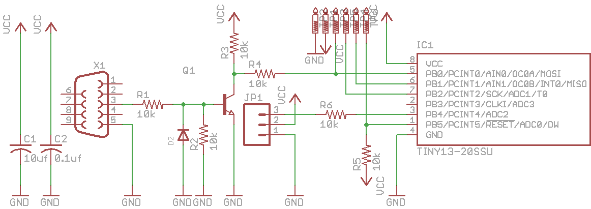
It should be noted that IR transmissions are usually sent on a modulated carrier (frequently 28kHz) and the overall waveform looks like a square wave made up of smaller square waves. The IR receiver is tuned to this specific carrier frequency, which prevents natural infrared radiation from interfering with the control signals. The signal that emerges from the IR receiver is stripped of this carrier frequency and looks like a normal square wave containing the binary data being sent to the receiver (usually a few address bits and a few data bits). By bypassing the IR receiver, my microcontroller will be able to send data without having to generate and modulate a carrier frequency.
The actual code that I'll be flashing to the Attiny hasn't been fully written yet. Until I know exactly what data is being transmitted by the remote control it won't make sense to try designing the program. In my next instalment I'll be probing the IR transmissions coming from the remote and coding the firmware to send commands to the control box.
This blog is powered by ikiwiki.