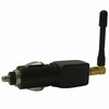
 A friend of mine recently acquired an inexpensive GPS jammer (pictured left) off a certain Chinese discount site to use in a report on GPS he made for our radio communications class.
 We were quite keen on learning what is was doing, so we attached it to a spectrum analyzer. Civilian GPS operates at 1575.42 MHz which is near the edge of this particular spectrum analyzer's measurement range, but we managed to produce pretty clean data anyways. This graph is centered on 1570MHz and spans about 40 MHz, clearly showing the jammer's signal from 1560-1580 MHz. The high peak on the upper end of the scale was some sort of transient effect which died down to a normal level after several tens of seconds. Although the graph looks as if it shows several peaks over a 20 MHz range, this is actually an illusion caused by the spectrum analyzer. In reality, the signal is a single peak, rapidly sweeping back and forth between the upper and lower range.
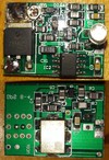
 Cheap electronics being what they are, the SMA antenna connector snapped right off (much to the relief of the FCC). The underside of the pads were actually still covered in solder paste that apparently had never been melted during relow. After that we decided to sacrifice it to some destructive testing. We pried open the case and found a double sided PCB containing a voltage regulator, 555 timer, 1.59 GHz VCO and a mess of filtering and support circuitry.

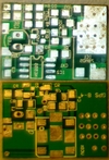
 I started by desoldering each SMD component individually using soldering tweezers and measuring each on an LCR meter. Once the board was empty and cleaned I stared really hard at it and used a combination of psychic powers and photoshop to determine how the pads were connected to one another.
Afterward I combined the connections and parts list and drew out the schematics in eagle. I recently found an eagle-to-LTspice export plugin, so it was pretty simple to run an analysis. Sure enough, the 555 timer was feeding a 1 MHz sawtooth wave into the control pin of the VCO to achieve the frequency sweep.
 Here's a picture of the circuit and a link to the eagle schematic.
Unfortunately, component L1 was of such a small inductance that our RCL meter was unable to measure it accurately. In addition, I wasn't able to verify what exactly component Q2 was. The small four pinned device had two oblique ground connections, and the remaining pair acted as a diode with a forward drop of about 1 volt. Although this would have been a good place to amplify the output signal with a transistor, this device was clearly unpowered. For now, I'm assuming that it was either a high speed diode or some type of transient voltage suppressant to protect the oscillator circuitry from any radio interference (ha!) that the transmitting antenna might pick up.